HV SERIES
Vertical Heat
Recovery Systems

HV SERIES, CONTINUOUS BLOWDOWN HEAT RECOVERY SYSTEMS
(3,000 – 12,000 lbs/hr capacity)
- SAVES ON FUEL COSTS – Payback is typically < 1 year.
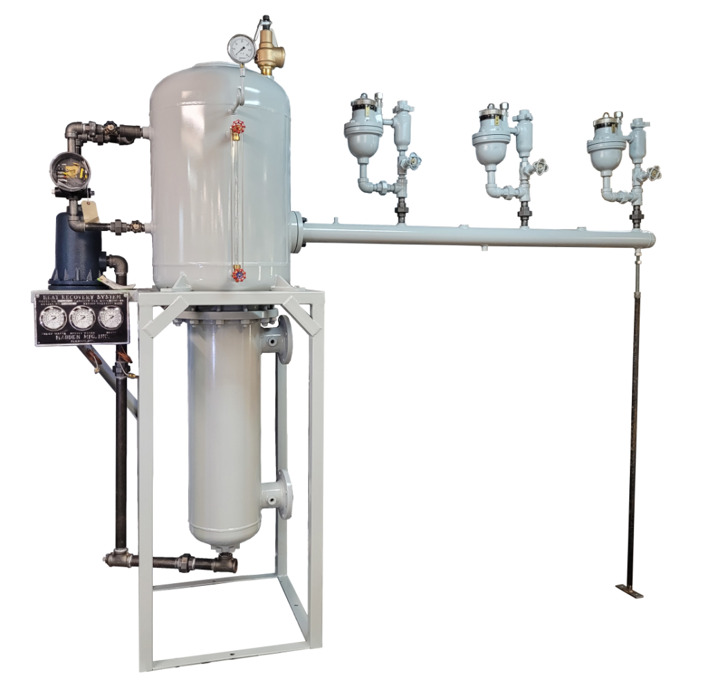
- COMPACT – (5) standard models available, offering capacities from 3,000 to 12,000 PPH. Uses 2 Sq. Ft. of floor space.
- CONSTRUCTION – ASME Div I, Sec VIII Vessels, 150 PSI @ 450 deg F. Mechanically actuated design requires little to no maintenance or operator assistance.
- FEATURES – Vertical coil type heat exchanger ensures no scale build up, gravity drains, custom manifold for multiple boilers, various level controllers available, temperature panel, high level alarm, and much more.
- Check out our Heat Recovery Brochure for more details.
- CONTACT US for selection/design assistance and pricing.
- OVERVIEW
- FEATURES
- SPECIFICATIONS
- RESOURCES
Madden Type HV Continuous Boiler Blowdown Heat Recovery Systems feature blowdown capacities up to 15,000 lbs. per hour. These HV series heat recovery systems work using the flash steam principle. When hot boiler blowdown enters the unit, it hits a baffle, this along with the pressure change causes some of the water to turn to flash steam. This flash steam is then sent off to the D/A tank to be reused. The remaining hot water is cooled with the U tube bundle at the bottom of the unit using cooling water. The cooled blowdown is then at statute limits for safe disposal and the resulting heated-up cooling water is now boiler feed water supplied to the D/A tank.
- Recovers 90% of lost heat
- Payback period of less than 12 months is common
- No solids build up
- ASME code welded flash tank and heat exchanger vessel, 150 psi construction Section VIII, Div.
- With National Board Serial Number and “U” stamp
- Safety pressure relief valve, normally set for 40 psi
- Flash steam outlet flange
- High water level alarm system (optional)
- Pressure Gauge
- Sight gauge for water level in flash tank
- Baffle creates water turbulence
- Manifold for mounting Orifice Meter or connecting other blowdown supply pipe, one or two manifolds can handle up to six boilers
- Madden Orifice Meter continuous blowdown control (optional). One meter required for each boiler
- 6” x 8” hand hole for float valve access and inspection
- Continuous flow balanced pressure float valve with 316 stainless steel float and trim is specifically designed for blowdown service
- Temperature gauge panel with three 3-1/2” gauges to monitor drain water, exchange water inlet and outlet temperatures, makes checking system efficiency easy
- Heat exchanger coil, four 7/8” copper tubes with bronze headers at each end. Designed to provide even distribution of hot water to all four tubes to maximize thermal transfer. (Optional 304 SS heat exchanger coil also available.)
- Exchanger shell with flanged exchange water inlet and outlet provides swirling action in the water. The turbulence assures exchange water contact with the coil surfaces and improved efficiency.
- Blowdown water discharge fitting and temperature bulb

HV Series
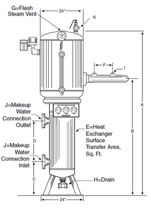
| Model Number | HV030 | HV050 | HV070 | HV090 | HV120 | HV150 |
|---|---|---|---|---|---|---|
| Blowdown Capacity lb/hr | 3,000 | 5,000 | 7,000 | 9,000 | 12,000 | 15,000 |
| A – (OAH) | 77″ | 83″ | 89″ | 95″ | 104″ | 124″ |
| B | 49-5/8″ | 55-5/8″ | 61-5/8″ | 67-5/8″ | 76-5/8″ | 94-5/8″ |
| C | 15″ | 15″ | 15″ | 15″ | 15″ | 15″ |
| D | 16-1/2″ | 22-1/2″ | 28-1/2″ | 34-1/2″ | 43-1/2″ | 61-1/2″ |
| E | 17 | 21 | 25 | 29 | 35 | 46 |
| F | 13″ | 13″ | 13″ | 13″ | 13″ | 13″ |
| G | 3″ FLG 1-1/2″ | 3″ FLG 1-1/2″ | 4″ FLG 1-1/2″ | 4″ FLG 1-1/2″ | 4″ FLG 1-1/2″ | 4″ FLG 1-1/2″ |
| H | NPTF | NPTF | NPTF | NPTF | NPTF | NPTF |
| I | *1″ | *1″ | *1″ | *1″ | *1″ | *1″ |
| J | 3″ FLG | 3″ FLG | 4″ FLG | 4″ FLG | 4″ FLG | 4″ FLG |
| K | 1-1/2″ | 2″ | 2″ | 2″ | 2″ | 2″ |
| Ship Weight in lbs. | 1,200 | 1,300 | 1,400 | 1,500 | 1,700 | 1,900 |
* I Dimension 1-1/4″ when Model 650 Orifice Meter is used
- HV Series Data Sheet
- HV Series Startup Guide
- Heat Recovery System, Fill in Proposal Data Sheet
- Generic Heat Recovery System Operator’s Manual
- INFORMATIVE DIAGRAM: Visualizing Adding Heat Recovery in Your Boiler Room
- INFORMATIVE DIAGRAM: Madden Heat Recovery SYSTEMS vs. Competitor’s ASSEMBLIES
- INFORMATIVE DIAGRAM: Continuous surface blowdown vs. bottom blowdown – Do’s & Dont’s
